
www.ptreview.co.uk
10
'26
Written on Modified on
ZEISS Introduces Virtual Clamping and Guided Holding Kit
ZEISS Industrial Quality Solutions has launched updates for its Virtual Clamping software application alongside a new Guided Holding Kit for component metrology fixtures.
www.zeiss.com
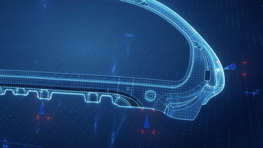
ZEISS Industrial Quality Solutions (ZEISS IQS) has introduced the latest product updates for Virtual Clamping, a specialized metrology application integrated within the ZEISS INSPECT 3D software platform. Operating in tandem with the newly engineered Guided Holding Kit, the system provides flexible clamping for geometric inspection across an array of injection-molded, die-cast, and sheet metal components.
Fixture Elimination and Automated Workflow Mechanics
The integration of the hardware and software subsystems eliminates the requirement for component-specific physical clamping fixtures across numerous industrial inspection operations. By substituting traditional dedicated fixtures with a universal positioning framework, the technology minimizes capital fixture costs, reduces measurement setup windows, and decreases labor overhead.
The underlying process relies on supporting components in a stress-free state while establishing reproducible positioning criteria for downstream optical scanning. The mechanical foundation utilizes the pre-existing Universal Pneumatic Clamping Device (UPD) infrastructure. By deploying the new Guided Holding Kit, the manufacturer expands the UPD hardware options to support automated metrology loops inside the ZEISS ScanBox optical 3D measuring machine, ensuring repeatable part mounting within robot-controlled inspection cells.
Semi-Automated Hardware Setup and Path Planning
The Guided Holding Kit secures target workpieces using up to four distinct physical contact points. The system features a semi-automated workflow managed through the central software layer:
- Virtual Enclosure Mapping: Depending on the physical dimensions and spatial orientation of the component, the software automatically calculates and inserts measuring plate extensions and protective collision bodies directly into the virtual measuring room environment.
- Sequence Generation: The system automatically renders a dedicated setup measurement sequence, permitting operators to repeatedly position parts in less than 10 minutes.
- Robot-Controlled Alignment: Following software-generated assembly blueprints, operators mount the universal holders onto the primary rotation table, executing the generated alignment measurement sequence via localized robot control to permit stress-free component inspection.
Parametric Deformation Modeling
The updated software suite incorporates advanced algorithms capable of evaluating a weight-force-compensated mesh, allowing components to be virtually clamped across simulated vehicle installation scenarios. The core mathematical framework for these structural calculations relies on a fully parametric deformation model referenced to the empirical optical measurement data, enabling realistic deflection inspection across critical sheet metal assemblies of a vehicle body.
Additional Context
This section details technical specifications and competitive benchmarking not included in the original news release.
Traditional inspection of flexible parts requires rigid physical checking fixtures constructed to clamp sheet metal or plastic parts to their nominal design intent. These specialized physical fixtures prevent full-surface optical line-of-sight access and introduce alignment variation based on manual clamping force deviations. To circumvent physical limitations, standard metrology inspection modules feature basic rigid-body alignments that cannot isolate structural manufacturing springback from gravity-induced sag.
Compared to traditional metrology inspection modules that require manual numerical adjustments or separate computer-aided design morphing modules, this updated approach combines hardware positioning with automatic virtual room collision generation. While typical metrology simulation modules require manual point-by-point definition of support pins, the inclusion of automated plate extension planning establishes a faster path to execution, reducing physical tool setup down to less than 10 minutes.
Furthermore, standard finite element analysis metrology plug-ins process unconstrained mesh scans externally, requiring operators to export heavy polygon datasets into third-party structural analysis software. Integrating a fully parametric deformation model natively within the metrology software loop enables direct actual-to-nominal comparisons of sheet metal assemblies. This architecture computes gravity compensation and virtual constraint states without exiting the primary inspection interface, eliminating data conversion errors and maintaining a complete parametric revision history for complex automotive sheet metal elements.
Edited by Romila DSilva, Induportals Editor, with AI assistance.
The updated software suite incorporates advanced algorithms capable of evaluating a weight-force-compensated mesh, allowing components to be virtually clamped across simulated vehicle installation scenarios. The core mathematical framework for these structural calculations relies on a fully parametric deformation model referenced to the empirical optical measurement data, enabling realistic deflection inspection across critical sheet metal assemblies of a vehicle body.
Additional Context
This section details technical specifications and competitive benchmarking not included in the original news release.
Traditional inspection of flexible parts requires rigid physical checking fixtures constructed to clamp sheet metal or plastic parts to their nominal design intent. These specialized physical fixtures prevent full-surface optical line-of-sight access and introduce alignment variation based on manual clamping force deviations. To circumvent physical limitations, standard metrology inspection modules feature basic rigid-body alignments that cannot isolate structural manufacturing springback from gravity-induced sag.
Compared to traditional metrology inspection modules that require manual numerical adjustments or separate computer-aided design morphing modules, this updated approach combines hardware positioning with automatic virtual room collision generation. While typical metrology simulation modules require manual point-by-point definition of support pins, the inclusion of automated plate extension planning establishes a faster path to execution, reducing physical tool setup down to less than 10 minutes.
Furthermore, standard finite element analysis metrology plug-ins process unconstrained mesh scans externally, requiring operators to export heavy polygon datasets into third-party structural analysis software. Integrating a fully parametric deformation model natively within the metrology software loop enables direct actual-to-nominal comparisons of sheet metal assemblies. This architecture computes gravity compensation and virtual constraint states without exiting the primary inspection interface, eliminating data conversion errors and maintaining a complete parametric revision history for complex automotive sheet metal elements.
Edited by Romila DSilva, Induportals Editor, with AI assistance.
